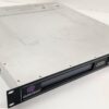
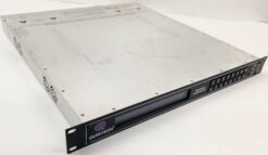
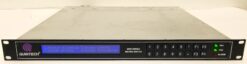
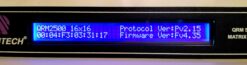

Quintech QRM250016X16CSFA000 Matrix Switching System

$1,700.00
Matrix Switching System
1 in stock
CompareQuintech QRM250016X16CSFA000 Matrix Switching System. Very good condition. Unit powers on (both or either PSU), passes self-test, display clear and bright, fans clean and quiet. Basic check O.K. No manual, cables or other accessories. Purchaser responsible for any certification if required, proper installation and use.
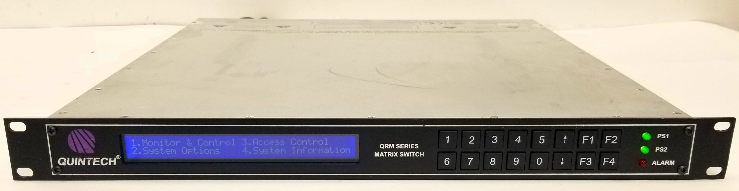
IF and L-band RF Routing Matrix Switch: QRM 2500
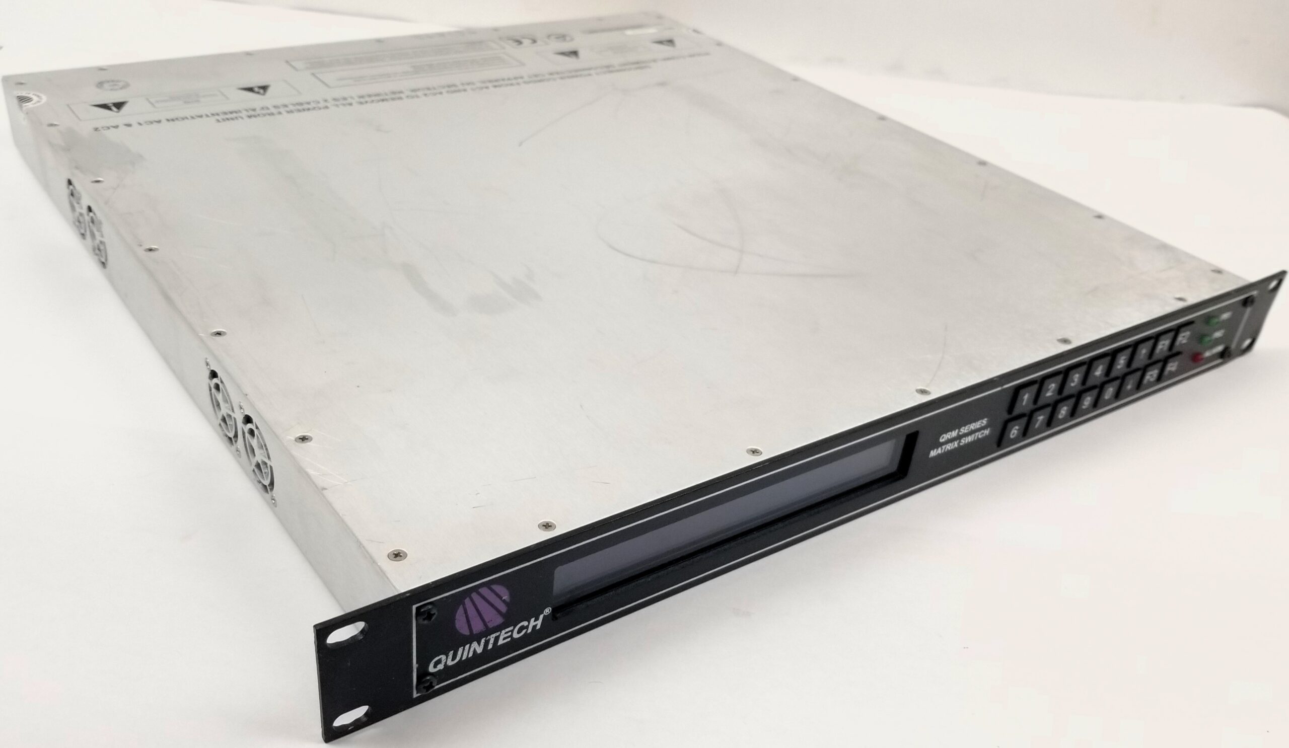
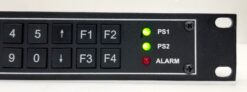
The QRM 2500 IF and L-band routing matrix features a 16×16 RF matrix routing in a compact 1 RU enclosure. The QRM also features Quintech’s latest Q-ROUTE and Q-SENSE technology, which provides maximum reliability with internal and external signal path redundancy and auto re-route capabilities. The QRM’s operating frequency range covers 50 MHz to 2150 MHz. It also offers manual and automatic AGC modes with a range of -15dB to +16 dB in 0.5 dB steps with optional LNB Power and individual port control to support all modulation formats. The front panel LED’s allow monitoring of power supply and alarm status information.
Features & Benefits
- Q-ROUTE Provides Internal Signal Path Redundancy by Automatically Re-routing Around a Failed Signal Path
- Q-SENSE Provides External Signal Path Redundancy by Automatic Switching of Back-up Input Signals
- Manual and Automatic AGC Modes with a Range of -15 dB to +16 dB in 0.5 Steps
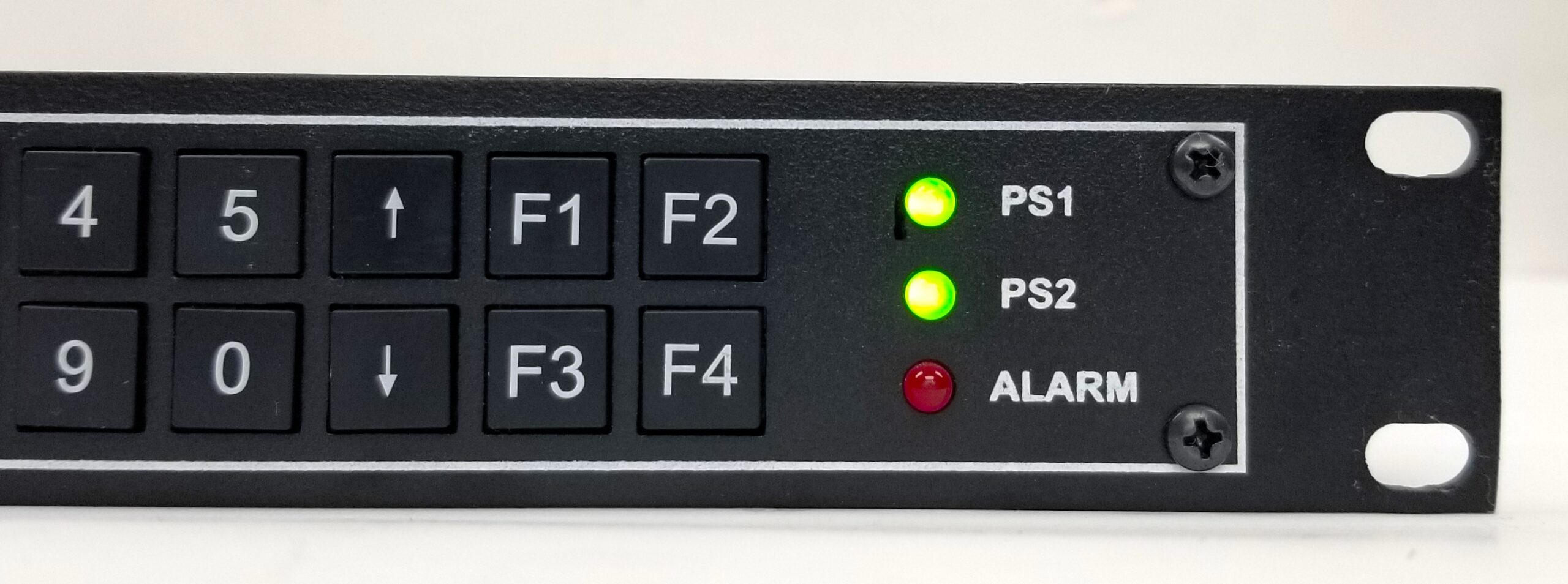
- Front Panel LED’s Allow Monitoring of Power Supply & Alarm Status
- Modular design allows for easy system installations and expansion
- Remotely controlled via web browser interface
- Solid state switches provide seamless (nanoseconds) switching speeds
- Maximize use of existing equipment with automated switching and scheduling’ no need for dedicated equipment
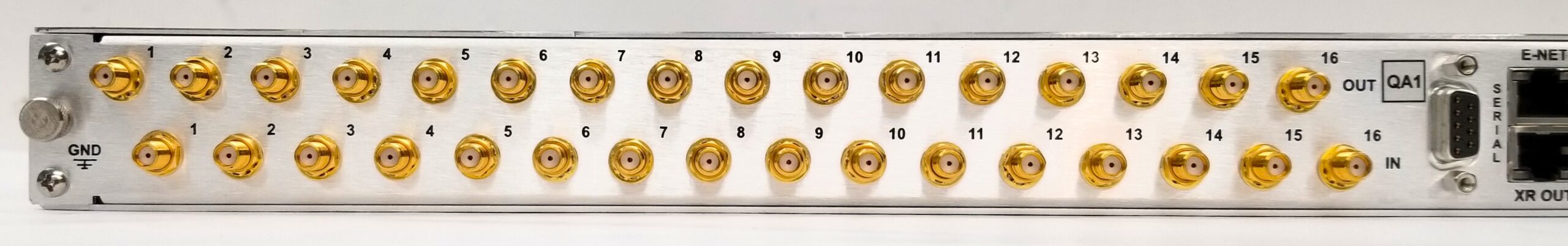
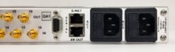
- The rear panel design facilitates structured cable routing, eliminating confusing tangles of cables
Specifications
| 16×16 Router | L-Band | IF |
|---|---|---|
| Operating Frequency: | (950-2150 MHz) | (50-200 MHz) |
| Frequency Response: | +/- 1.5
+/- 0.4 dB Over any 36 MHz channel |
+/- 2
+/- 0.6 dB Over any 36 MHz channel |
| Isolation | ||
| (input to input): | 65 dB | 65 dB |
| (output to output): | 60 dB | 60 dB |
| (input to output): | 50 dB Typ. | 55 dB Typ. |
| RF Input Power | -10 dB to -70 dB | -10 dB to -70 dB |
| Gain Range (manual mode) | -15 dBm to +16 dB in 0.5 dB steps | -15 dBm to +16 dB in 0.5 dB steps |
| Impedance | 50 Ω or 75 Ω | 50 Ω or 75 Ω |
| Output AGC level | -10 dBm to -50 dBm | -10 dBm to -50 dBm |
| Max. RF Output Power: | -10 dBm | -10 dBm |
| Input P1dB | +2 dBm | -3 dBm |
| OIP3 | +10 dBm | +8 dBm |
| Input Return Loss: | 14 dB | 14 dB |
| Output Return Loss: | 14 dB | 14 dB |
| Noise Figure: | <18 dB @ 0dB
<9.5 dB @ 16 dB |
<18 dB @ 0dB
<9.5 dB @ 16 dB |
| Configurations: | 8×8, 8×16, 16×8, 16×16 | |
| RF Connectors: | BNC (50 or 75 Ω), type “F” , SMA Connectors | |
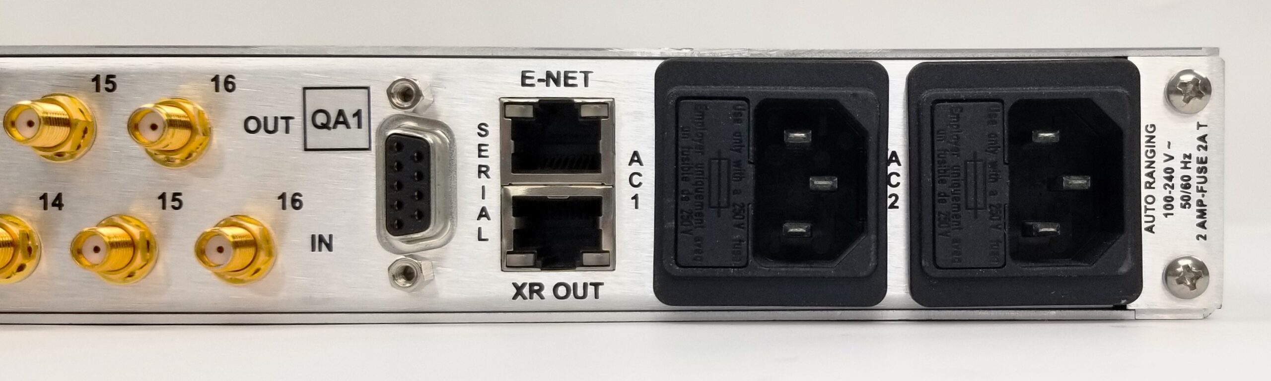
| AC Input Power: | Auto ranging 100-240 VAC, 50/60 Hz | |
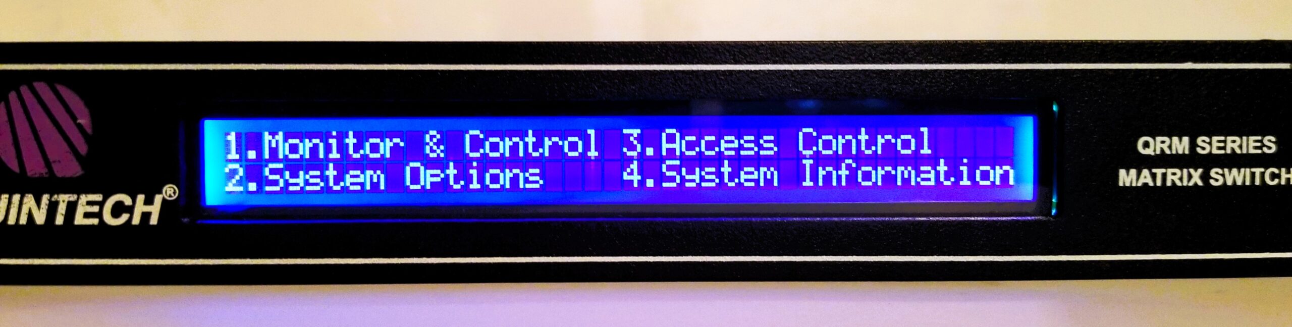
| Local Control: | Front panel keypad with LCD display | |
| PC Remote Control: | RS-232. RS 485, SNMP, Telnet or TCP/IP via customer supplied PC2 | |
| Software: | Basic PC compatible operating software and command protocol included | |
| Mechanical: | 16×16 in 1 RU 1.75″ H x 19″ W x 18.5″ D | |
| Weight | 15 lbs |
|---|---|
| Dimensions | 24 × 24 × 8 in |
Related products